
Operation Manual Part 2

Digital Liquid Cooled UHF
TV Equipment
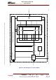
Description / Test points / Location of units
9946 V1
45321648.01 104 A E
preliminary
85 / 131
Numéro / Number Doc. Rev. Lan
g
u.
16/06/2006
Pa
g
e
Information contained is this document is confidential, is THOMSON property and cannot be disclosed in whatever form without prior written authorization of THOMSON.
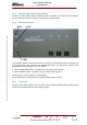
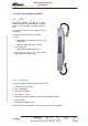
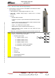
3.10.4. Indicator lamps and message displays
♦ A LED indicator on the front panel of the amplifier card indicates the status
of the transmitter as follows :
• LED extinguished : voltage supply has failed or is ≤ 24V,
• green LED : amplifier voltage supply is present and it is working
satisfactorily,
• red LED :
- transistor failure as follows :
I < 2.4 A for a group of 4 power transistors with polarisation (P input >
-4dBm)
- overdrive (over current or power protection system activated and fault
stored : 45 A for 4 double transistors),
- P input > -4 to -3dBm and P output <250W
- SWR protection system activated and fault stored (≥ 2 ),
- thermal protection system activated and fault stored (air input
temperature
≥ 60°C),
• orange LED : internal power supply absent in the protection system card.
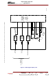
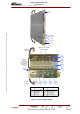
NOTE:
The PCL «AMPLIFIERS» window displays the status
conditions of a power amplifier as follows :
• transistor current values:
- T1 : amplifier modules 1 and 2,
- T2 : amplifier modules 3 and 4,
- T3 : amplifier modules 5 and 6,
- T4 : amplifier modules 7 and 8,
- T5 : transistors in class AB drive amplifier,
- T6 : transistors in class A preamplifier,
• ON,
• general fault,
• SWR fault,
• overdrive fault,
• internal temperature fault,
• presence/absence.
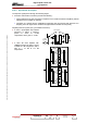
T1
T2
T3
T4
T5T6