
Operation Manual Part 2

Digital Liquid Cooled UHF
TV Equipment
Description / Test points / Location of units
9946 V1
45321648.01 104 A E
preliminary
84 / 131
Numéro / Number Doc. Rev. Lan
g
u.
16/06/2006
Pa
g
e
Information contained is this document is confidential, is THOMSON property and cannot be disclosed in whatever form without prior written authorization of THOMSON.
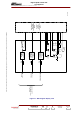
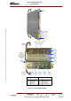
Module 1
Module 2
Module 7
Module 8
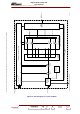
2100W AMPLIFIER
Drive amplifier
AB class
Preamplifier
A class
(62 dBm)
RF signal output
1 x 8 WAY
SPLITTER
RF signal input
THERMISTOR
To CPU board
(throught/ amplifier power supply and multiplex board)
LDMOS UHF amplifier modules
4 WAY
OUTPUT
COMBINER
Amplifier power
supply
AGC voltage adjustment
Monitoring signals
32V
Pi2
V alim.
V polar.
POWER SUPPLY DISTRIBUTION BOARD
POWER AMPLIFIER
63dB gain
Fw2
Fw1 RW
INTERFACE AND
PROTECTION
BOARD
06/105 (e)
V polar.
Figure 19 : Block diagram of a power amplifier