
Operation Manual Part 2

Digital Liquid Cooled UHF
TV Equipment
Description / Test points / Location of units
9946 V1
45321648.01 104 A E
preliminary
83 / 131
Numéro / Number Doc. Rev. Lan
g
u.
16/06/2006
Pa
g
e
Information contained is this document is confidential, is THOMSON property and cannot be disclosed in whatever form without prior written authorization of THOMSON.
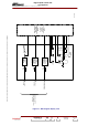
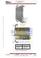
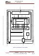
♦ a 1 x 8 way distribution unit to split the
input power from the class AB amplifier
into 8 amplifier signals,
♦ 2100 W amplifier consisting of eight class
AB amplifier modules with LDMOS
transistors which provides a minimum
power of 4 x 570W with a gain of 13 dB at
1 dB of compression,
♦ a coupling unit which recombines the
outputs of the 8 amplifier modules. This
coupling unit is a four-way combiner with
three directional couplers arranged along
the output line. This facilitates the sampling
of the output and return power values
inside the amplifier. The sample provides
the necessary signals for the protection
circuits and the amplifier AGC reference
signal. The output power sample signal
(Pi) is sent to the front panel for
monitoring.
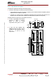
Monitoring
connector on front
panel
Return wave
Forward wave
To protection
board
Slope
compensation
LDMOS
LDMOS
Module 5
Module 7
Module 8
Module 6
Module 3
Module 4
LDMOS
LDMOS
Module 1
Module 2
1600W amplifier card
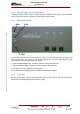
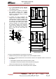
The power supply distribution card provides the following :
♦ distribution of all power and bias supplies for the various amplifier sub-units,
♦ the taking of sample measurements of the transistor currents in the amplifier modules. This serves
two purposes :
• the amplifier is provided with a fail-safe protection system,
• the amplifier currents are measured via the Central Processing Unit.
These current values are sent to the amplifier protection card.
♦ the interface for the status LED on the front panel of the amplifier.