
Operation Manual Part 2

Digital Liquid Cooled UHF
TV Equipment
Description / Test points / Location of units
9946 V1
45321648.01 104 A E
preliminary
82 / 131
Numéro / Number Doc. Rev. Lan
g
u.
16/06/2006
Pa
g
e
Information contained is this document is confidential, is THOMSON property and cannot be disclosed in whatever form without prior written authorization of THOMSON.
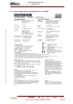
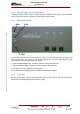
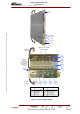
3.10.3. Operational description
The input RF signal passes through the following stages
♦ Protection and interface card which provides the following :
• manual adjustment of gain and phase to equalise for the variations between amplifiers (internal
adjustment not accessible to operator),
• generation of a voltage which is adjustable for automatic gain control (AGC) with reference to a
sampling of the RF signal at the combiner unit (adjustment accessible on front panel),
amplifier protection system (see § «Surveillance devices»).
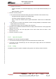
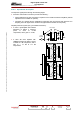
♦ A class A preamplifier with LDMOS
transistors to deliver a minimum
power of 20 W at 0.2 dB
compression, with a gain G
≥ 37 dB,
♦ A class AB drive amplifier with
LDMOS transistors to deliver a power
of 220W at 1 dB compression, with a
gain G
≥ 12 dB at 0.2 dB
compression.
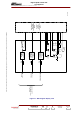
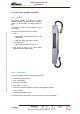
3 dB coupler
LDMOS
LDMOS
Hybrid
amplifier
LDMOS
LDMOS
LDMOS
LDMOS
Module 1
Module 2