
Operation Manual Part 2

Digital Liquid Cooled UHF
TV Equipment
Description / Test points / Location of units
9946 V1
45321648.01 104 A E
preliminary
81 / 131
Numéro / Number Doc. Rev. Lan
g
u.
16/06/2006
Pa
g
e
Information contained is this document is confidential, is THOMSON property and cannot be disclosed in whatever form without prior written authorization of THOMSON.
06/082(e)
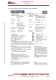
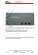
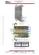
J2
RF Output
J104
RF Input
Power supply
Connector
J106 Side
J107 Side
06/083(e)
External connections
Protection & interface board
Class A preamplifier2 ways Wilkinson
Class AB amplifier
Splitter 8 Ways
External connections
Power supply distribution board
4 ways combiner
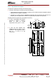
Printed circuit board
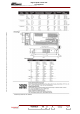
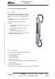
AGC voltage adjustment
Two-coloured indicator
Holes to fix the special
carrying handle
Hydraulic
connector
Never carry
amplifier
by the handle
on the front panel
of the amplifier.
Use the special
handle
Hydraulic
connector
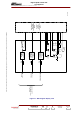
A2
A4
A5
A6
A11A7A9A8
R164
DS1
A5
Item
A11
A2
A4
A5
A6
Item
A7
A8
A9
R164
DS1
Figure 18 : UHF Amplifier 1600W