
Operation Manual Part 2

Digital Liquid Cooled UHF
TV Equipment
Description / Test points / Location of units
9946 V1
45321648.01 104 A E
preliminary
79 / 131
Numéro / Number Doc. Rev. Lan
g
u.
16/06/2006
Pa
g
e
Information contained is this document is confidential, is THOMSON property and cannot be disclosed in whatever form without prior written authorization of THOMSON.
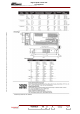
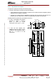
• connector J5 in case of:
- analogue transmitter: for sound SWR signal (only in case of split channel transmitter) or not
used,
- digital transmitter: not used
♦ Connector J6 which provides :
• the connection with the Central Processing Unit (via the exciter/CPU interconnection card) :
- the input illumination signals for PCL indicator lamps,
- the output command signals (On, Off, Reset),
- input of output and reflected power signal measurement values from the reflectometer
probes.
• the connection of the RS 232 serial link for data exchange between the transmitter control
system and the PCL touch screen,
• for input power supply to the PCL (display card and screen),
♦ Connector J7 for the RS 232 serial link between the display card and the touch screen (signal data
originate in the CPU),
♦ Connector J8 for the +24 V DC input power for the touch screen from the exciter / CPU
interconnection card,
♦ Connector J9 which is not used.
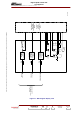
3.9.6.7. Input power supplies
The display card is fed with the following supplies:
♦ +5 V DC from the CPU power supply card via the exciter/CPU interconnection card,
♦ +12 V and -12 V DC, with back-ups, from the exciter power supply cards via the exciter/CPU
interconnection card.
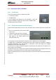
3.9.6.8. Cooling
The display card does not require a separate cooling system; it is cooled by natural convection.