
Operation Manual Part 2

Digital Liquid Cooled UHF
TV Equipment
Description / Test points / Location of units
9946 V1
45321648.01 104 A E
preliminary
78 / 131
Numéro / Number Doc. Rev. Lan
g
u.
16/06/2006
Pa
g
e
Information contained is this document is confidential, is THOMSON property and cannot be disclosed in whatever form without prior written authorization of THOMSON.
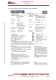
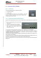
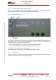
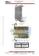
3.9.6. The display card 45324176
3.9.6.1. Outline
The display card performs the following functions :
♦ it sends commands to the equipment units,
♦ it demodulates the monitoring signals received from the directional probes in the RF connections to
the transmitter antenna and displays them,
♦ it acts as the interface between the LCD screen and the transmitter control system.
3.9.6.2. Operational description
Refer to the entitled paragraph « Operational description » of the sub-assembly LOCAL CONTROL
PANEL.
3.9.6.3. Indicator lamps
There are no status indicator lamps to indicate the status conditions of the display card. The indicator
lamps on the front of the PCL indicate the overall status of the transmitter.
3.9.6.4. Adjustment controls and Test et points
Refer to entitled paragraphs « Adjustment controls » and « Test et points » of the sub-assembly
LOCAL CONTROL PANEL.
3.9.6.5. Internal protective devices
The display card has no need of internal protective devices.
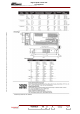
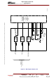
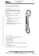
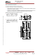
3.9.6.6. Connections and data transfer
The display card has the following connectors:
♦ Connectors for envelope signal from reflectometer probes :
• connector J1 in case of:
- analogue transmitter: for sound signal,
- digital transmitter: not used
• connector J2 in case of:
- analogue transmitter: for vision signal,
- digital transmitter: for RF signal,
• connector J3, for antenna SWR signal,
• connector J4 in case of:
- analogue transmitter: for vision SWR signal (only in case of split channel transmitter) or not
used,
- digital transmitter: for SWR signal