
Operation Manual Part 2

Digital Liquid Cooled UHF
TV Equipment
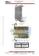
Description / Test points / Location of units
9946 V1
45321648.01 104 A E
preliminary
77 / 131
Numéro / Number Doc. Rev. Lan
g
u.
16/06/2006
Pa
g
e
Information contained is this document is confidential, is THOMSON property and cannot be disclosed in whatever form without prior written authorization of THOMSON.
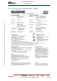
3.9.3. Indicator lamps and message displays
There are no status indicator lamps to indicate the status conditions of the display card. The indicator
lamps on the front of the PCL indicate the overall status of the transmitter.
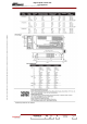
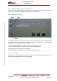
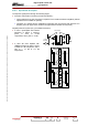
3.9.4. Adjustment controls
R435
TEST
R475
The sensitivity controls on the front of the PCL are used to set the parameters which are displayed by
the bar graph on the PCL and in the "RF REFLECTED LEVEL" and "RF LEVEL" windows; these
adjustments set the input signals and are as follows :
♦ R435 “POWER INDICATION” : sensitivity control for output power indication,
♦ R475 “ANTENNA VSWR” : sensitivity control for antenna SWR indication.
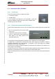
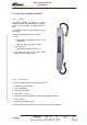
The output power level is displayed on the bargraph.
Return SWR values are displayed on the "RF REFLECTED LEVEL" window.
3.9.5. Test points
Pressing on the "TEST" button on the front panel of the PCL with a pointed object will check that the
indicator lamps and bargraph LED’s are working properly.