
Operation Manual Part 2

Digital Liquid Cooled UHF
TV Equipment
Description / Test points / Location of units
9946 V1
45321648.01 104 A E
preliminary
75 / 131
Numéro / Number Doc. Rev. Lan
g
u.
16/06/2006
Pa
g
e
Information contained is this document is confidential, is THOMSON property and cannot be disclosed in whatever form without prior written authorization of THOMSON.
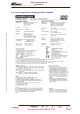
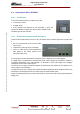
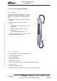
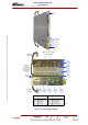
3.9. Control panel (PCL) 45333047
3.9.1. Architecture
The Local Control Panel (PCL) consists of two units:
♦ an LCD touch screen,
♦ a display circuit.
It is the principal user interface for the transmitter. It gives the
operator the facilities to display the various status conditions of the
transmitter and its main sub-units.
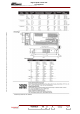
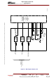
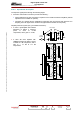
3.9.2. Architecture and operational description
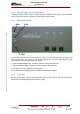
There are three push buttons on the PCL (On, Off, Reset). Each command signal from a push button
is:
♦ fed to a set-reset latch circuit to avoid contact
bounce; then,
♦ shaped into a pulse via a timer; and finally,
♦ sent to a buffer memory which transmits the
data pulses to the control system of the
transmitter (CPU card).
The output power level as measured by a directive probe is displayed on an LED bargraph.
A voltage which is proportional to the measured power value is applied to converters to produce a
progressive illumination of the LED bargraph; an illumination of the total length of the bargraph
corresponds to the nominal output power.
The values for the output and reflected signals as measured by the probes are sent directly to the
control system of the transmitter.
The indicator lamps on the display card indicate transmitter operational status conditions and they are
activated by command signals from the control system of the transmitter (CPU).
An RS 232 serial link from the CPU which carries data to and from the LCD screen passes through the
display card.