
Operation Manual Part 2


Digital Liquid Cooled UHF
TV Equipment
Description / Test points / Location of units
9946 V1
45321648.01 104 A E
preliminary
72 / 131
Numéro / Number Doc. Rev. Lan
g
u.
16/06/2006
Pa
g
e
Information contained is this document is confidential, is THOMSON property and cannot be disclosed in whatever form without prior written authorization of THOMSON.
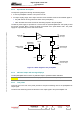
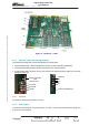
• connections via the data bus with MODAP A, (via connector J50 of the interconnection card),
• connections to the remote user interface data bus (RS 232 bus), (via connectors J11 or J40 of
the interconnection card),
• connections to the data bus to the synthesizers (via connector J50 of the interconnection card),
♦ connector J21 :
• for output status signals to a hard wired remote user interface (via connectors J2 and J3 of the
interconnection card),
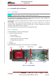
♦ connector P6 which has :
• connections via the data bus with MODAP B, (via connector J150 of the interconnection card),
• connections via the data bus with external equipment using RS 232 or RS 485 serial links (via
connectors J70, J80, J90, J100 of the interconnection card).
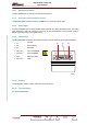
3.7.8. Cooling
The Central Processing Unit is cooled by the exciter cooling system. Input air is drawn into the cooling
chamber which is situated below the frame which houses the exciter cards ; the air then circulates
through the cards.