
Operation Manual Part 2


Digital Liquid Cooled UHF
TV Equipment
Description / Test points / Location of units
9946 V1
45321648.01 104 A E
preliminary
71 / 131
Numéro / Number Doc. Rev. Lan
g
u.
16/06/2006
Pa
g
e
Information contained is this document is confidential, is THOMSON property and cannot be disclosed in whatever form without prior written authorization of THOMSON.
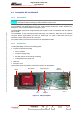
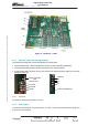
3.7.7. Connections and data transfer
The Central Processing Unit has the following connectors:
On front panel :
♦
connector P1 : spare,
♦ connector P2 : for serial link (RS 232C) connection with the "Log book" terminal,
♦ connector P3 : spare,
♦ Connector P5: for Ethernet network,
P1
Location for PCMCIA card
P2
P3
CPU Reset
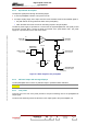
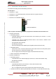
In the rear panel, the following connectors plug into the exciter/CPU interconnection card :
♦
connector J6 which has :
• the following outputs :
- command signals from the hard wired remote user interface (via connector J1 on the
interconnection card),
- command to RF relay for switching between exciter A and exciter B, situated on the
exciter/CPU interconnection card,
- the synthesizer reset command,
- RF switching commands,
- the on/off command for the amplifier power supplies (via interconnection card).
• the following inputs :
- values for the vision, sound and antenna RF power levels sent from the RF probes (via the
PCL and connector J7 of the interconnection card),
- the +5 V supply from the CPU power supply card (via interconnection card),
• the bus connections to the multiplex card,
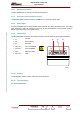
♦ connector J20 which has :
• the following outputs :
- commands to the PCL indicator lamps (via connector J7 of the interconnection card),
- RF switching commands,
• the following inputs :
- commands from the PCL (via connector J7 of the interconnection card),
- presence signals from the exciters,
- the +12 V supply from the CPU power supply card (via interconnection card),
• connections to the PCL data bus (bus RS 232), (via connector J7 of the interconnection card),