
Operation Manual Part 2


Digital Liquid Cooled UHF
TV Equipment
Description / Test points / Location of units
9946 V1
45321648.01 104 A E
preliminary
70 / 131
Numéro / Number Doc. Rev. Lan
g
u.
16/06/2006
Pa
g
e
Information contained is this document is confidential, is THOMSON property and cannot be disclosed in whatever form without prior written authorization of THOMSON.
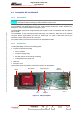
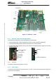
Figure 16 : CPU board – TH860
3.7.4. Indicator lamps and message displays
The Central Processing Unit card has the following on its front panel :
♦ a green indicator lamp : when this flashes the memory access is operating satisfactorily,
♦ an orange/yellow indicator lamp: when this is lit up the CPU card is powered,
♦ an red indicator lamp: when this is lit up CPU board is not operating properly (light up a short time
during CPU start up).
yellow LED
red LED
Green LED
switch not used
Ethernet connection
RJ45
P1
Location for PCMCIA card
P2
P3
CPU Reset
3.7.5. Controls
The switch on the CPU front panel is not used.
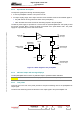
3.7.6. Power input
The Central Processing Unit card is powered by +5 V and +12 V DC from the CPU power supply card
in the front of the transmitter.