
Operation Manual Part 2


Digital Liquid Cooled UHF
TV Equipment
Description / Test points / Location of units
9946 V1
45321648.01 104 A E
preliminary
67 / 131
Numéro / Number Doc. Rev. Lan
g
u.
16/06/2006
Pa
g
e
Information contained is this document is confidential, is THOMSON property and cannot be disclosed in whatever form without prior written authorization of THOMSON.
3.6.6. Adjustment controls
The pre-amplifier has no controls on its front and rear panels.
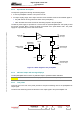
3.6.7. Protection and surveillance devices
The RF preamplifier module is fused by an CMS fuse F1 (1A) at the +24VDC input.
3.6.8. Power input
The RF preamplifier gets its single phase mains feed from the mains distribution panel. The mains
input connector is fed from connector J10 or J11 on the EXCITER/CPU interconnection board in
bottom of the transmitter control system frame.
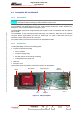
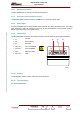
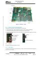
3.6.9. Connections
The RF preamplifier module has one SUB-D connector (Type B 3W13) on its rear panel as follows:
• A1
: RF input.
• A2
: RF monitoring.
• A3
: RF output.
• Pins 1 & 6
: 240 V AC
Neutral.
• Pins 8 & 3
: 240 V AC
Phase.
• Pin 5
Detection output.
• Pins 7 & 2
: GND.
A1
A3
A2
04/038
3.6.10. Cooling
The preamplifier module could be cooled by natural convection.
3.6.11. Transportability
No special requirements.