
Operation Manual Part 2


Digital Liquid Cooled UHF
TV Equipment
Description / Test points / Location of units
9946 V1
45321648.01 104 A E
preliminary
66 / 131
Numéro / Number Doc. Rev. Lan
g
u.
16/06/2006
Pa
g
e
Information contained is this document is confidential, is THOMSON property and cannot be disclosed in whatever form without prior written authorization of THOMSON.
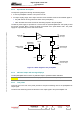
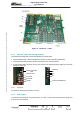
3.6.3. Operational description
The input RF signal passes through the following stages.
♦ A class A preamplifier to deliver a rms power of 0.8 W.
♦ An output coupling stage, with a slope correction circuit and which sends an RF feedback signal to:
• the peak detector circuit (provides the status of the preamplifier),
• which the latter then sends out from RF monitoring outputs to the pre-amplifier.
The built-in power supply G1 provides 24 V used to bias the hybrid amplifier MA1 and equally to feed
the DC/DC converter MA3. It supply the buffer circuit MA2 of the peak detector CR1. The power
supply G1 is protected by fuse F1 from short-circuits.
A1
Entrée RF
RF input
Sortie RF
RF output
A2
Sortie test RF
RF test output
A3
CR1
Sortie détection
Detection output
MA2
G1
DC/DCMA3
5V-DC
F1
24V-DC
Entrée secteur
Mains input
Alimentation
Power supply
04/030 (f-e)
AC
MA1
Figure 15 : Block diagram of the preamplifier
3.6.4. Indicator lamps and message displays
The RF preamplifier does not have any indicator lamps or operational status indicators.
NOTE :
The PCL «EXCITER» window displays the status condition of a preamplifier.
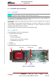
3.6.5. Test points
Connector A2 on the rear of the panel provides a test point monitoring feed of the preamplifier RF
output signal.
The level of the monitoring feed is 20 dB down on the output signal to the power amplifier unit.