
Operation Manual Part 2


Digital Liquid Cooled UHF
TV Equipment
Description / Test points / Location of units
9946 V1
45321648.01 104 A E
preliminary
65 / 131
Numéro / Number Doc. Rev. Lan
g
u.
16/06/2006
Pa
g
e
Information contained is this document is confidential, is THOMSON property and cannot be disclosed in whatever form without prior written authorization of THOMSON.
3.6. Preamplifier RF Unit 45326079
3.6.1. Presentation
NOTE : The preamplifier Module is “Hot Swap” compatible. Defective PA Modules may be removed
and replaced without shutting the entire transmitter system down.
The RF preamplifier is designed to amplify residual side band modulated television analogue signals
for all standards, and digital signals in DTV (US - ATSC standard and Europe - DVB-T standard). It is
designed to work in UHF transmitters for bands IV and V.
The preamplifier output power is approximately 0,8 W peak at 1 dB of compression with an minimum
gain of 20 dB.
The preamplifier is fully solid-state (Hybrid technology). The module is fitted with an the interface
connector SUB-D (type B3W13) for 240V AC mains input, for output of fault data used by the
transmitter control system and for RF connectors.
One small Handle is used to insert and remove the preamplifier module.
3.6.2. Architecture
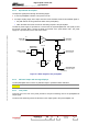
The RF preamplifier consists of the following parts :
♦ A printed circuit board including :
• class A amplifier,
• an output coupling stage,
• the peak detector circuit and RF monitoring,
• an integrated power supply unit.
♦ Heat sink
♦ Protection cover
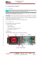
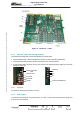
Figure below shows the positions of the various parts in the preamplifier.
Handle
PSU (AC/DC) DC/DC Converter
F1
Fuse
RF
Amplifier
04/040 (e)
SUB-D
Connector
Figure 14 : UHF preamplifier