
Operation Manual Part 2


Digital Liquid Cooled UHF
TV Equipment
Description / Test points / Location of units
9946 V1
45321648.01 104 A E
preliminary
63 / 131
Numéro / Number Doc. Rev. Lan
g
u.
16/06/2006
Pa
g
e
Information contained is this document is confidential, is THOMSON property and cannot be disclosed in whatever form without prior written authorization of THOMSON.
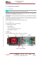
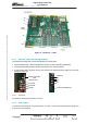
3.5.6. Connections and data transfer
The mother board connectors are as follows:
♦ on one side : connectors J6, J12, J20, J21 to the CPU,
♦ on the other side:
• J6.1, J12.1, J20.1, J21.1: to the daughter board,
• J13 : connection to a GPS receiver (option) which provides sync signals for the modulator,
• J30 : connects the CPU with the exciter RF switching relays,
• J40 : connects to remote user interface via RS232 serial link,
• J50 : connects CPU to exciter A,
• J70 : connects CPU to external DVB -T modulator (exciter A),
• J80 : connects CPU or exciter A to external equipment via RS232 or RS485
serial link (provisional),
• J90 : connects CPU to external DVB -T modulator (exciter B),
• J100 : connects CPU or exciter B to external equipment via RS232 or RS485
serial link (provisional),
• J150 : connects CPU to exciter B.
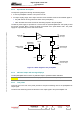
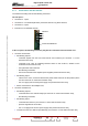
The daughter board connectors are as follows:
♦ on one side : connectors J6, J12, J20, J21 to the mother board,
♦ on the other face it has the following connectors for connections with the rest of the transmitter :
• J1, for input command signals from a hard wired remote user interface to the Central
Processing Unit card,
• J2, J3, for output status signals from the Central Processing Unit card to a hard wired remote
user interface,
• J4, for the transfer of command signals, in addition to status and fault signals between the
various transmitter units (other than the exciter and CPU) and the multiplex card,
• J5, for the input of messages from the multiplex card about faults in the various transmitter units
(other than the exciter and CPU),
• J7, for data exchange with the PCL and for feeding very low voltage supplies to the PCL,
• J8, not used,
• J9, for the input of very low voltage supplies from the CPU power supply card,
• J10
• J11, for connections via the serial link between the CPU and a remote user interface (RS232
with JBUS protocol).
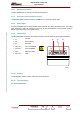
3.5.7. Cooling
The exciter/CPU interconnection card is cooled by natural convection.