
Operation Manual Part 2

Digital Liquid Cooled UHF
TV Equipment
Description / Test points / Location of units
9946 V1
45321648.01 104 A E
preliminary
54 / 131
Numéro / Number Doc. Rev. Lan
g
u.
16/06/2006
Pa
g
e
Information contained is this document is confidential, is THOMSON property and cannot be disclosed in whatever form without prior written authorization of THOMSON.
A
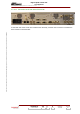
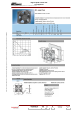
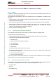
Main power supply input :90 to
254 volts AC, 47 to 63 hertz
B
2 RJ45 connexions for ethernet
and ethernet TS information in
connexion with the digital board.
C
10 MHz 50 ohms frequency
reference input connected to
digital board
D
Timing reference 1 pps
connected to digital board
06/097(e-f)
A BCDE
LEFT SIDE OF THE RACK
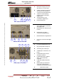
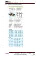
E
External GPS input
F
Double input and double output
opto coupled ports in connexion
with digital board
G
DB9 RS232 UTC reference input
for GPS
H
DB9 RS232 Local CM in
connexion with digital board.
I
DB9 RS232 data for digital board.
06/098(e-f)
F GHIJ
MIDDLE SIDE OF THE RACK
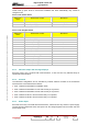
J
Can bus in connexion with digital
board
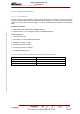
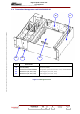
K
Low priority DVB-ASI input TS
L
High priority DVB ASI input TS
M
Automatic gain control input
N
VSWR input in connexion to TS
board
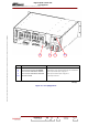
O
Feedback RF input for linear
automatic correction
P
Feedback RF input (-15dBm+/-
5dB) no linear automatic
correction.
Q
0 dBm with 45dB shoulder RF
output
R
DB9 Double input and double
output opto coupled ports in
connexion with switch/ALE board
06/099(e-f)
K LMNO
PQRS
RIGHT SIDE OF THE RACK
S
Optional ASI output