
Operation Manual Part 1


Digital Liquid Cooled UHF
TV Equipment
Description / Test points / Location of units
9946 V1
45321648.01 104 A E
preliminary
35 / 131
Numéro / Number Doc. Rev. Lan
g
u.
16/06/2006
Pa
g
e
Information contained is this document is confidential, is THOMSON property and cannot be disclosed in whatever form without prior written authorization of THOMSON.
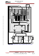
3. Description / Test points / Location of units
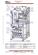
3.1. System architecture and location of transmitter units
The Dual Drive version of the transmitter consists of the following units:
♦ a unit containing two exciters in a redundant switchover system whereby a faulty exciter is replaced
by the other. After digital processing, it transposes the input MPEG signals into a RF output.
Each digital exciter consists of:
• A SIRIUS rack with :
A DVB-T (Europe) modulator board , ATSC (America) modulator board or MédiaFLO modulator
board
a processing signal board,
an RF synthesiser,
a preamplifier,
a Very Low Voltage power supply,
• In the management rack, a RF amplifier (for DVB-T and ATSC modulator only)
♦ a coaxial relay and its 50 Ohms load so that one of the two digital exciters can be switched on RF
amplifier channel.
♦ an RF amplifier way,
♦ a filter unit which filters the RF signal,
♦ a control system as follows:
• A Central Processing Unit (CPU) which supervises the operation of the transmitter electronics
units depending on operator commands and the status conditions in the units.
• the very low voltage power supply for the CPU and the PCL,
• an exciter/CPU interconnection card,
♦ a multiplex card which is the connection unit between the Central Processing Unit and the main
transmitter electronic units,
♦ a Local Control Panel (PCL) which controls the data interchange between the operator and the
transmitter,
♦ a Mains Distribution Panel which provides the mains feeds for the various transmitter power
supplies,
♦ the power supplies for the RF amplifiers,
♦ the cooling system for the Exciter/CPU system.
The following associated external sub-systems for the SD/DD transmitters combine together to form a
complete transmission operation:
♦ an external cooling system to cool the transmitter,
♦ an input three-phase mains supply,
♦ an external changeover system so that the transmitter can be switched between a dummy load and
the antenna,