
Operation Manual Part 1

Digital Liquid Cooled UHF
TV Equipment
Detailed operational description
9946 V1
45321648.01 104 A E
preliminary
16 / 131
Numéro / Number Doc. Rev. Lan
g
u.
16/06/2006
Pa
g
e
Information contained is this document is confidential, is THOMSON property and cannot be disclosed in whatever form without prior written authorization of THOMSON.
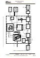
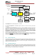
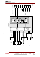
2.2.4. Amplification of the RF signal
The output RF signals from the exciters are low power signals. This signal is sent to the inputs of the
amplifiers, which are mounted in trays and are all connected in parallel.
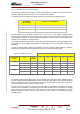
The following shows the number of amplifier modules as a function of the transmitter power.
RMS POWER
(BEFORE FILTER)
NUMBER OF RF AMPLIFIERS
3,1 kW 6 amplifiers
5,2 kW 10 amplifiers
6,3 kW 12 amplifiers
Each RF output from the amplifier modules is fed to a type F.I.C.S. (Full Isolated Coupling System)
combiner which guarantees a mutual isolation of the order of 26 dB. This coupling system allows an
on-air amplifier module to be removed without shutting down the transmission. Thus a faulty output
amplifier can be replaced by a spare amplifier.
The amplifier modules are powered by 10 kW plug-in power supplies with very high reliability, which
provide 250 A at 28 V (voltage programmable on 3 bits from 24 to 31 V), (one power supply for two
amplifiers).
The use of several power supplies and amplifiers in the RF amplifier channel leads to a minimum
degradation of power performance parameters when any of these units become faulty.
EXAMPLE FOR DVB-T TRANSMITTER NUMBER OF FAULTY UNITS
TRANSMITTER
POWER
UNIT TOTAL
NUMBER
1 2 3 4 5
Amplifier 8 -1.16 dB -2.5 dB -4.08 dB -6 dB -8.52 dB 3.2kW
Power supply 4 -2.5 dB -6 dB -12 dB
Amplifier 12 -0.76 dB -1.6 dB -2.5 dB -3.5 dB -4.7 dB 5kW
Power supply 6 -1.6 dB -3.5 dB -6 dB -9.5 dB -15.5 dB
Amplifier 16 -0.64 dB -1.16 dB -1.8 dB -2.5 dB -3.25 dB 6.5kW
Power supply 8 -1.16 dB -2.5 dB -4.08 dB -6 dB -8.52 dB
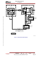
AGC acting on the power level compensates for loss of gain in the amplifiers.
An Automatic Gain Control (AGC) loop is used to regulate the power output. Each amplifier provides
an AGC voltage (detected voltage) which is fed to an analogue "OR" gate on the transmitter multiplex
board. These data are sent to the TX board of the exciter, on which there is an RF gain control in the
form of an attenuator which controls the output power.
The "OR" gate ensures that the exciter output power signal is controlled by the largest of the AGC
voltages from the amplifiers. Consequently the RF power amplifier which is delivering the largest
power level is taken as the reference for the AGC loop. This means that all amplifiers are equally
driven irrespective of failures in one or more of them; this also ensures a constant linearity for the
amplifier channel.