
Operation Manual Part 1

Digital Liquid Cooled UHF
TV Equipment
Detailed operational description
9946 V1
45321648.01 104 A E
preliminary
15 / 131
Numéro / Number Doc. Rev. Lan
g
u.
16/06/2006
Pa
g
e
Information contained is this document is confidential, is THOMSON property and cannot be disclosed in whatever form without prior written authorization of THOMSON.
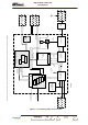
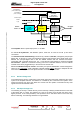
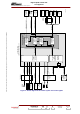
I / Q
Q
I
Pre-
amplifier
DIGITAL
MPEG - TS
RF Feedback
(from TX output)
06/114(e)
External inputs
10 MHz
1 pps
Synthesizer
Signal
Processing
COFDM
or 8VSB
or MediaFLO
Modulator
RF Output
COFDM only
PSU
+5V +24V
Local external
terminal (VT)
CPU
or
Board Interface
To Control and
Monitoring
System
Feedback
ALE Switch
Wide band
Down/conversion
RS232
Complex
Up/Converter
IF
RF Feedback
(from RF filter output)
A Preamplifier allows a peak output power of + 40 dBm.
An internal RF Synthesizer, with different options, feeds the TX card for the RF up and down
conversions.
The Internal Control and Monitoring is achieved by a serial link, SPI bus, managed by the principal
digital card. In this way It is the Communication Interface node between all the digital cards of the
SIRIUS. The principal digital card is also the SIRIUS interface with the external environment:
Transmitter C/M or external terminal (VT, PC...). This external communication is achieved using RS
232 interfaces: (Ethernet or CAN Bus in factory) one for the transmitter interface, one for a external
terminal which can be plugged directly in the front face of the DAP unit.
Use of a redundant transport stream is ensured by the optional «BRA/DASI» function designed to
select one of 2 ASI inputs
. It also integrates a Bit Rate Adapter (BRA) designed to adapt the bit rate
fed to the modulator, by means of the synchronisation clock called «Synchro IN».
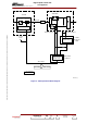
2.2.2. Exciter change-over
In the Double Drive version, coaxial relay routes the RF signal from the exciter selected by the control
system to the amplifier channels. This switcher is controlled by the "command control system" in the
Central Processing Unit, which also takes into account both the operator commands and any fault
signals sent from the selected exciter.
2.2.3. ASI input change-over
The switching of the way 1 towards the way 2 and conversely is always possible whatever is the state
of the stream ASI on 2 ways. The switching of a way on the other one is left with the choice of the
digital processor of the card (modulator). The processor has to ask about alarms of the other way
before commuting. The switching seamless is not guaranteed.