
Operation Manual Part 1

Digital Liquid Cooled UHF
TV Equipment
Generale description
9946 V1
45321648.01 104 A E
preliminary
10 / 131
Numéro / Number Doc. Rev. Lan
g
u.
16/06/2006
Pa
g
e
Information contained is this document is confidential, is THOMSON property and cannot be disclosed in whatever form without prior written authorization of THOMSON.
RF
signal
RF amplifier
channel
CABINET (S)
(*) Only applies to the DD version
06/112 (e)
Channel 1A
CENTRAL
PROCESSING
UNIT
RF
FILTER
CENTRAL CONTROL
SYSTEM CRATE
50Ω
MPEG input
Channel 2A
Channel 1B
Channel 2B
CONTROL
PANEL
RF
preamplifier A
RF
signal "A"
Adapt.
EXCITER
A
BASIC
TRANSMITTER A
BASIC
TRANSMITTER B
RF
preamplifier B
RF
signal "B"
*
Adapt.
EXCITER
B
*
*
*
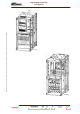
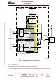
Figure 1 : Simplified transmitter block diagram
1.2.2. Architecture
The Dual Drive version of the transmitter consists of the following units:
♦ a unit containing two exciters in a redundant switchover system whereby a faulty exciter is replaced
by the other. After digital processing, it transposes the input MPEG signals into a RF output.