
User's Manual Part 3

Backplane/Interface Boards - 123 -
®
Affinity LBD-200C-N1 Transmitter
Product Manual
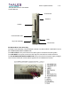
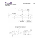
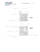
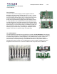
Driver Backplane
The Driver Section Power Supply module supplies the Driver
Backplane and Upconverter module with 5V
DC, 12 VDC, –12 VDC,
and data through 48-pin DIN connections (1). The main power to
the Driver Section Power Supply plug-in is delivered through a six-
position blind mating connector (2) that is supplied by a push
button switch (3) activated by plugging the Power Supply module
in. Pins attached to the rear panel of the modules provide module
grounding through the grounding sockets (4). A five-position single
row header (5) and a 24-position dual row header (7) allow external
data exchange. Two six-position single row headers (6) supply the
RF modules with power and communications. A redundant driver
assembly may be achieved by connecting two backplane boards
together via the two five-position single row headers (8).
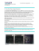
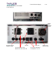
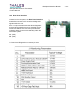
16.3 PA Backplane
The PA Modules are electrically and physically connected to the PA Backplane when plugged
into the Chassis assembly. The PA Backplane contains float-mounted, blind-mating receptacles,
and blind-mating headers for module alignment. The PA Backplane provides +48V
DC and
ground for the PA Module segments. The PA Backplane also contains RS485 multidrop
communication connectivity used by the PA Module assemblies. A two-position Dual Inline
Package (DIP) switch located on the PA Backplane is used to enable or disable control and
diagnostic access via the RJ11 connector located on the front panel of the PA Modules.