
User's Manual Part 3


Status Control and Monitoring System - 160 -
®
Affinity LBD-200C-N1 Transmitter
Product Manual
24 Status Control and Monitoring Systems
This is now Omnitronics SL81
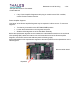
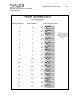
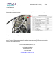
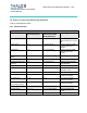
24.1 Parallel Interface
UHF Affinity® Remote Control Interface
Controls Cabinet
Connector/Pin(s)
407755-01
Interconnect Cable
Connector/Pin(s)
Signal Type
RF On/Off J3-1 P3-1 (pair 1 RED) Latched contact closure to
CMD Common (pin 13) for
Off
Power Lower J3-2 P3-2 (pair 1 BLK) Contact closure to CMD
Common (pin 13) to
activate
Power Raise J3-3 P3-3 (pair 2 RED) Contact closure to DMD
Common (pin 13) to
activate
Command Common
(GND)
J3-13 P3-13 (pair 6 BLK) Tied to Gnd inside TX
Status
Transport Stream Input
presence
J3-4 P3-4 (pair 2 BLK) Contact closure between
pins 4&5=Fault
J3-5 P3-5 (pair 3 RED)
Exciter RF Output Fault J3-6 P3-6 (pair 3 BLK) Contact closure between
pins 6&7 =Fault
J3-7 P3-7 (pair 4 RED)
Power Supply Fault J3-8 P3-8 (pair 4 BLK) TTL Low (0V)=Fault
(reference to GND)
Pre-Amp Fault J3-14 P3-14 TTL Low (0V)=Fault
(reference to GND)
Power Amp Fault
(Not currently active)
J3-10 P3-10 (pair 5 RED) TTL Low (0V)=Fault
(reference to GND)
Metering
Forward Power J3-11 (+) P3-11 (+) (pair 5 BLK) 0-4VDC between pins
11&12
J3-12 (-) P3-12 (-) (pair 6 RED)