
User's Manual Part 3

Setup & Detailed Alignment Procedures - 147 -
Affinity® LBD-200C-N1 Transmitter
Product Manual
2. In order to calibrate the reflected meter, swap the forward sample and reflected sample
cables on detector module.
3. Set NORMAL DEBUG MODE = 1(For a complete explanation of debug modes see
DOC#25-0021). The screen will auto refresh. Note, that the variable names no longer
represent actual parameter. DOC# 25-0021 explains the function of each parameter
under the various debug modes. (Normal debug mode = 1 is used for meter calibration.)
4. Under the monitored variables frame, read values displayed in the third row. The value
in the cell titled LOW is first multiplied by 256 then added to the value in the cell titled
HIGH. The resulting value from this operation is now entered into SYSTEM
REFLECTED POWER REFERENCE parameter. This completes the reflect meter
calibration.
5. Return the cables to normal position.
6. Set HEALTH SNAPSHOT 65535 to clear any faults.
22.6 Calibrate Fast Reflected Shut Down
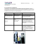
1. Sample the Transmitter output using an inline variable attenuator. Set the level to -5dBm
and connect this signal to the reflected port of TRU RMS detector module.
2. Raise level slowly until the preamplifier LCD display of reflected power reads 15%.
3. Lower the FAST REFLECTED THRESHOLD until the power is reduced by approx. 6dB
(this power reduction is pre determined) A typical value of fast reflected threshold =
1000. This threshold must be precise. Use smaller calibrations steps when reaching
near the value of 1000.
4. Once tripped, it will stay at reduced power. To verify or to recalibrate, lower the sample
and reset the module; use the reset button on the EMSET window for this purpose.
5. Verify that you can raise the reflected power percentage to at least 10% without the
transmitter tripping into the 6dB protection mode. Also, exceed the 15% mark to activate
the protection system. Again, reset the module back into normal operation when this test
is completed.
6. Set system reflected power percent limit to = 25.
7. Return all cables to normal position.
8. Set HEALTH SNAPSHOT 65535 to clear any faults.
22.7 Non-linear Precorrection
1. Navigate to the menu for non-linear calibration on the exciter front panel; this is located
under the F5 button on the keypad located below the display window [Press F5 once].
The feedback sample should be connected prior to the channel filter (default location).
2. Observe that the feedback level is Normal; see feedback level indicator (typical level is –
15dBm).
3. Apply a one-shot or place the correction in adaptive mode; allow a few seconds for
automatic correction.
4. Observe the shoulder level; ensure it is within tolerable limits (i.e.
t34dB).