
User's Manual Part 3


Quick Start Procedure - 143 -
Affinity® LBD-200C-N1 Transmitter
Product Manual
21 The Affinity® Quick Start Procedure
Each Thales transmitter is factory calibrated, and requires only a minimum start-up procedure to
ensure proper operation. The appropriate steps for the installation of the Affinity® transmitter
system and its ancillary equipment must have been performed prior to initiating this procedure.
Please consult the installation and cabling sections of this manual before powering up any
equipment. Verifying that all cables and electrical connections are in place is crucial. Read this
section entirely, along with the calibration section, prior to beginning the transmitter power
initiation process.
1. Start by ensuring that all of the amplifier modules are turned off via the front panel key
switches.
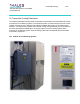
2. Apply AC power to the UPS system; follow the manufacture’s turn on guidelines.
3. Apply AC power to the site management system; follow the manufacture’s turn on
guidelines.
4. Apply AC power to the satellite receiver; follow the manufacture’s turn on guidelines.
Ensure a proper ASI feed is available to the Sirius DVB-H Exciter.
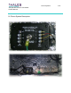
5. Switch on AC power to the Affinity® Upconverter amplifier chassis(s). Observe that the
AC fan has begun to operate (fan noise will be heard).
6. Turn on the 48V Front-End Power Supplies; all plug-in modules should indicate proper
DC output via their LED display. Also, observe that the driver sections including the
multi-output Power Supply Plug-In and Upconverter have begun their initialization (a
small time lag is normal -- under 5 seconds typical).
7. Switch on the Sirius DVB-H Exciter. Using the exciter front panel MMI, turn off adaptive
pre-correction if enabled and place in flat response mode (first go to frozen mode then
go to flat mode).
8. If available, use a spectrum analyzer to verify the exciter output level -18dBm
r 1dB.
Adjust if required. Observe the exciter output, perform cancellation of LO or image
rejection via local MMI or SIRUIS setup GUI interface (this is a factory calibration and
should not be required).
9. Connect exciter output to the Upconverter amplifier chassis (UCA) UHF input.
10. Ensure 1GHz Local Oscillator connection via exciter and UCA.
11. Connect power meter to output coupler.
12. Ensure that the transmitter output is connected to an appropriate sized 50-ohm station
load. Note: the return loss of the load should be greater than 15 dB at minimum.
13. Switch on all power amplifier (PA) front panel key switches while observing the power
meter.
14. Using a power meter, ensure proper power output. Also, if available, observe channel
spectrum output shoulder performance; shoulder should not exceed -29dBc from flat top,
RES BW 30kHz VBW 3kHz. Span 15MHz. marker at 1672.5MHz delta
r2.64MHz.