
User's Manual Part 3

Backplane/Interface Boards - 127 -
Affinity
®
LBD-200C-N1 Transmitter
Product Manual
Remote Serial Interface
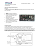
External high-level management systems connect to the Affinity® transmitter using the
transmitter Remote RS-485 interface. The electrical interface consists of: an RJ-11 jack located
on the Affinity® rear panel, a wire harness located inside the Affinity® chassis, and the RS-485
transceiver circuit located on the MSI circuit board assembly. SNMP management is provided
through the Omnitronix SNMP Device Server.
Local Bus System Controller
The MSI acts as a master on the Local RS-485 network located inside the Affinity® chassis. As
the master on the network, the MSI sends query and command messages to the slave devices
on the Local network, and receives responses from the slave devices. The Upconverter plug-in
is a slave device.
The Local bus support circuitry consists of:
Auxiliary Serial Port
An RS-232 transceiver, and dedicated MCU and CPLD circuits are provided on the MSI to
support an auxiliary RS-232 serial port (aux port). The port system consists of the transceiver
and controller circuits on MSI connector J13, and harnessing to the rear panel DB-9 male
connector. The auxiliary serial port is typically used to interface a modulator to the Affinity®
transmitter.
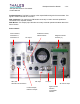
Master Reference Oscillator
The Master Reference Oscillator (MRO) system on the MSI receives a 10 MHz reference input
on MSI SMA connector J17. The MRO phase-locked loop (PLL), which contains an on-board
VCO, locks to the reference input. The VCO output signal is fed to two SM connectors, J16 and
J19. These are used to feed the Affinity® Local Oscillator and the modulator (optional). A
tracking mechanism is provided that follows the control voltage applied to the VCO. Should the
10 MHz reference input be removed, the tracking holds the VCO at the last stable position of the
VCO. This helps maintain the transmitter on frequency, even after loss of reference input.
PAS Manager
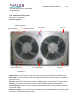
The Power Amplifier Segments (PAS) are contained in the same chassis as the MSI. This group
of amplifiers is called a “quad”.
The PAS Manager of the MSI protects the amplifiers from damage that could occur following
failure or removal. When an amplifier fails, the output power of the transmitter is reduced. The
transmitter ALC will attempt to correct the reduction in power by increasing the drive level
applied to the remaining amplifiers. Since this can result in overdriving the remaining amplifiers
and potentially damaging the device(s), the PAS Manager reduces the ALC level to a factory-
calibrated level. The transmitter power is reduced predictably (Fast ALC Reduction). The PAS
status signals are monitored on connector J7 of the MSI. Failed PAS location numbers are
stored in a CPLD register and read by the Main MCU for monitoring and fault notification.