
User's Manual Part 3

Backplane/Interface Boards - 125 -
®
Affinity LBD-200C-N1 Transmitter
Product Manual
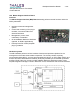
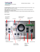
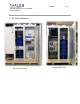
16.5 RS-485 Communication Board
An RS-485 Communication Board is mounted to the inside rear of the Driver Section. The
board monitors the RS-485 communication traffic on the system bus. A common
computer/master control station can monitor up to 32 RS-485 devices on the network.
The RS-485 Communication Board is equipped with two RJ11 6-pin telephone type receptacles.
The cables used to daisy chain (parallel) the RS-485 devices to the host are shielded double
twisted pair.
A mini double-pole double-throw (DPDT) dipswitch labeled NETWORK END TERMINATION is
accessible on the RS-485 Communication Board from the back panel of the Driver Section. In
an RS-485 network, all RS-485 devices in the daisy chain series, with the exception of the last
RS-485 device in the network, have the dipswitch set to OUT. The last RS-485 device in the
network has the switch set to TERM. Placing the switch in TERM terminates the communication
bus with the required impedance.
RS-485 Communication Board