
User's Manual Part 2

Power Amplifier Module - 114 -
®
Affinity LBD-200C-N1 Transmitter
Product Manual
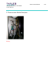
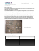
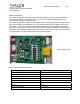
PA Module Front Panel Assembly
The PA Module Front Panel Assembly houses an RS-232 COMM PORT, a bi-color
POWER/FAULT LED, and the ON/LOCKED--OFF/UNLOCKED key lock assembly. The PA
Module is also equipped with a heatsink, installation handle and thumbscrews.
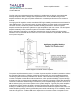
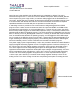
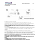
The RS-232 COMM PORT 6-pin RJ11 telephone type connector is used to interface with a
serial host computer. This interface allows a host computer to control and monitor functions of
the PA Module.
The bi-color POWER/FAULT LED is used as a visual indicator for PA Module power and fault
conditions. A green LED indicates power to the PA Module. A red LED indicates a fault
condition.
The key lock assembly is used to secure the PA Module to the Chassis assembly.
In the ON/LOCKED position, the PA Module is locked into the chassis assembly and receiving
power. The PA Module cannot be removed from the chassis while in the locked position.
In the OFF/UNLOCKED position, operating power to the PA Module is disabled and the PA
Module may be removed from the chassis for service or “Hot Swap” replacement. This key lock
assembly does not affect Affinity® transmitter power.
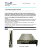
The Heatsink is a folded-fin heat-sinking device used to dissipate heat generated by the PA
Module.
The Handle is used to insert and remove the PA Module segment.
The Thumbscrews are used to secure the PA Module segment to the Chassis.