
User's Manual Part 2


Power Amplifier Module - 111 -
®
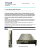
Affinity LBD-200C-N1 Transmitter
Product Manual
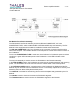
serial I/O port is also available, but the RS-232 driver is disabled by default. This port is
interfaced through an RJ-11 connector on the PA Module front panel. When the ENA_RS-232
control input line is given a logic-LOW (i.e. interface cable plugged into the PA Module RJ-11
connector), the RS-232 port is enabled. At this time the RS-485 port is disabled causing a loss
of communication with the RS-485 network. The same PA Module command and response
capabilities available on the RS-485 port are provided on the RS-232 port.
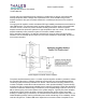
A ‘watchdog’ function is provided on the control board to safeguard against loss of MCU
program control. Under normal circumstances, MCU IC input lines RESET and XIRQ will be
provided with a logic-HIGH by an on-board watchdog IC. If Jumper JK3 is in place, the CPLD
device must provide a toggle in the CPLD WDI Output line every 1.6 seconds to indicate to the
watchdog that the MCU is operating properly. The CPLD will interpret a PG3/WDI input from the
MCU, or activity on the UC_RS485_ENA control line, or activity on the RS-485 communications
lines, as indications that the MCU is operating properly, and will toggle the CPLD WDI output
line. If a toggle in the WDI line does not occur within 1.6 seconds it is assumed that MCU is no
longer executing the desired program properly. The watchdog will drive low the XORZ signal,
which will ultimately result in a reset of the MCU and a restart to the MCU program.
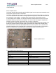
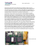
Two power supply inputs of approximately +10V
DC are provided to the Microcontroller Board to
supply the digital and analog regulator circuits. The digital regulator circuits are fused by F1 at
the +10V
DC input. A linear voltage regulator provides the +5VDC used for the digital circuitry.
The +5V
DC digital circuit has a separate ground plane for the digital devices. A switching
regulator and associated components develop DC output voltages of approximately ±14.5V
DC,
which is regulated by linear regulators to +12V
DC and –12VDC for various digital and analog
circuits. The +5V
DC analog regulator is supplied from a +10VDC separate from the digital
+10V
DC input, and is fused by F2. Another linear voltage regulator develops +5VDC for the
analog circuits. The +5V
DC analog circuits have a separate ground-plane for analog devices.
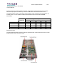
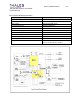
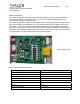
Microcontroller board