
User's Manual Part 2

Power Amplifier Module - 109 -
®
Affinity LBD-200C-N1 Transmitter
Product Manual
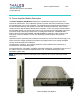
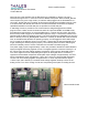
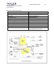
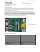
Power Amplifier Board
The Power Amplifier Board amplifies the RF INPUT signal from the upconverter assembly to the
output power requirement of the transmitter.
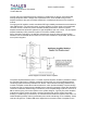
The Power Amplifier Board has a high-gain architecture providing 38.5 dB of gain, an output of
1-dB, and compression of 53.5 dBm. The signal passes through a pin diode attenuator that sets
the overall gain of the amplifier. A variable phase shifter sets the overall phase insertion.
In the first stage of the amplifier, a 3-dB hybrid provides a reliable load to the driver and a flat
broadband frequency response to the amplifier. The second and third stages of amplification
efficiently provide the proper output power with a minimum of distortion.
A 3 dB combining system provides for a low output Voltage Standing Wave Ratio (VSWR). The
directional coupler provides a sample signal proportional to the forward and reflected power.
This measurement ensures that the amplifier delivers the correct power. An IC measures the
operating temperature of the amplifier that is monitored by the microcontroller. The amplifier is
placed in a faulted state if the temperature exceeds a limit set by the microcontroller.
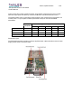
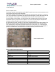
Power Amplifier Board Specifications
Parameter Specification
Input Voltage 48VDC
Input Current 19.8 Amps
RF Gain 38.5 dB
Output Power 47 dBm (COFDM signal)
Flatness (BW 392 MHz) ± 0.75 dB
Input VSWR 1: 1.6
Output VSWR 1: 1.5
Operating Temperature 0°to 43°C
Power Amplifier board