
User's Manual Part 2

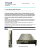

Power Amplifier Module - 107 -
®
Affinity LBD-200C-N1 Transmitter
Product Manual
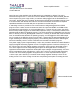
The PA chain uses segmented power amplifiers in parallel that are directly interchangeable.
Affinity® amplifiers utilize a design that is optimized for the 1670-1675MHz range. Each
amplifier module is also gain and phase matched for consistent performance from module to
module.
The high gain RF amplifier module uses GaAs FET high reliability transistors that are biased for
class AB operation. The inherent linearity of these amplifiers, and the quality of the associated
correction circuits, combine to product excellent linearity performance. Each final power
amplifier module has protection systems for high temperature and over-current. The final power
amplifier assembly has a protection system for excessive VSWR conditions.
Due to transistor redundancy, the standby arrangements are such that an abrupt and total
shutdown of the transmitter due to failure of one or more transistors is implausible; the same is
true of power supplies.
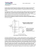
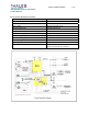
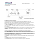
Block diagram of final RF Power Amplifier
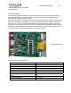
The power amplifier assembly uses “n” number of power amplifier modules in parallel to achieve
the required output power. Amplifier combining is through the very low-loss patented passive
combining system exclusively available from Thales. This combiner technology allows for any
number of amplifier combinations without restriction, which provides flexibility in system design,
and reduces cost by putting power scalability at the customer’s fingertips. Thales also allows the
customer to select the desired margin built into the power amplifier stage; options of 0.3 and 1.5
dB are offered giving cost control options to the system designer. Typically two power amplifier
modules are used to achieve 50 watts, 16 power amplifiers are used to achieve 400 watts
building in 1.5dB margin (or headroom). A controlled soft fail method is applied in the event of a
faulted amplifier(s) safely reducing transmitter power while maintaining on-air availability. Power
reduction ranges from 1.5dB to 6dB and is dependant on the total number of amplifiers in the