
User's Manual Part 2

Exciter Configuration Description - 59 -
®
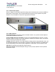
Affinity LBD-200C-N1 Transmitter
Product Manual
DAP
TM
and converts them to an analog on-channel RF signal. An internal synthesizer controls
the conversion frequency. The RF local oscillator is always locked by means of a very precise
internal 10 MHz Oven Controlled Crystal Oscillator (OCXO). It can also be locked to an external
10 MHz frequency reference. This synthesizer module also provides the 1000MHz RF local
oscillator for a second upconversion within the transmitter. In this conversion stage, the 670-
675MHz UHF output is translated to the proper on-channel output frequency of 1670-1675MHz
A feedback sample from the RF signal at the output of the transmitter is used to control the
shoulders, the linear correction process, and to monitor the quality of the signal.
The CUDC also receives a gain control command from the return path interface for automatic
gain control (AGC). The modulator has the capability to adjust its output power in manual mode
(when AGC is disabled). The AGC signal is used to adjust the output power of the RF signal
from the exciter and to maintain it within specified limits.
The RF signal output of the transmitter is sampled, down converted back to UHF, using the
same 1000MHz local oscillator, and fed back to the exciter. This RF output sample is fed into
the return path interface contained in the CUDU where it is demodulated. The I and Q reference
signals are derived from a reference demodulator also contained in the return path interface.
They are the base-band I and Q signals of the transmitter output sample. These signals are fed
into the DAP™ processing function in order to correct the transmitter system for linear and non-
linear distortions.
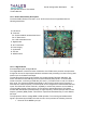
The TS Board receives I & Q output signals and a clock reference from the digital board. These
I & Q signals are processed by the TS Board including: Clipping, Linear Equalization, Non
Linear adaptive pre-correction. The Clipping function limits the magnitude of the vector above a
given threshold. The magnitudes higher than the threshold are replaced by the threshold
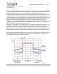
complex value. The non-linear automatic pre-correction function computes the best shoulder
level at the output of the transmitter. The process is based on a Look Up Table (LUT) that is
loaded from an iterative measurement of the shoulder level. The complex base-band outputs of
the LUT are up-converted to the IF frequency. The complex IF frequency signals are converted
in the analog domain, filtered, amplified and transposed to the UHF Tx Board. A daughter board
installed on the TS Board performs the up conversion function. External feedback from the RF
signal at the output of the transmitter is used to control the shoulder, the linear correction
process, and to monitor the quality of the signal. The TS Board then processes the feedback. A
DVB-H Enhanced QoS measurement board (optional) is plugged into the TS Board. It is a real
time demodulator board used to efficiently monitor the incoming stream. An additional DVB-H
hardware demodulator can be used for quality measurement at the output of the transmitter
(optional).
10.1.5.3 Power Supply
An internal power supply provides +12volts, -12 volts, +5 volts and + 3,3 volts to the exciter
subassemblies.
10.1.5.4 UHF Synthesizer
A digitally programmable synthesizer is provided to deliver a sinusoidal signal at the transmitting
frequency of between 430 and 900 MHz, with an output level of 10 dBm / 50 ohms. This module