
User's Manual Part 2


Driver Section - 101 -
®
Affinity LBD-200C-N1 Transmitter
Product Manual
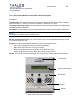
From this point, pressing SEL will scroll through the list again.
At any point to exit and return to the default display, press the ESC key as many times as
necessary.
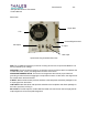
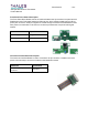
Distribution Board
The Distribution board consists of a 14-1/4” x 3-1/2” circuit board that is screwed to the
Upconverter chassis. The circuitry on this board permits the processing of signals, and the
control over the flow between the Upconverter plug-in IF/RF modules and the microprocessor
board, the front panel through connector J2, and the display boards through J6. The Distribution
board and Interface board, via connector J1, allow communication between the Upconverter
Plug-In Module and the Backplane board. The module is divided into two parts: digital
processing and analog processing.
Digital Processing Circuits
U3 (when present), U4, U6, U8, U9, U10 and U11
and related passive components form the digital
portion of this module. An extension of the
microprocessor board capabilities would sufficiently
classify their function.
Analog Processing Circuits
All components, other than those listed above, are classified as the analog-processing block.
Amplification and flow control of signals, as well as sensing of current and power levels, are the
main tasks performed by these components.
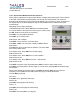
Working principle
After powered up, the Distribution board starts receiving commands from the microprocessor via
connectors J100-J103. One-by-one the voltages needed to control the IF/RF modules are set to
a pre-working level. IF AGC reference, IF threshold, IF equalization, RF ALC reference,
reflected power threshold, and power limiter voltages are set through the D/A converters U6,
U8, U9 and U10 as well as the operational amplifiers U13, U14, U15 and U16. The commands
originating from the microprocessor board are processed and delivered to Q3 and Q4, which
turn on the GaA medium power devices present in the UHF Driver Amp assembly and IF-UHF
sub module (if present).
Voltages proportional to the current drawn by the UHF Driver Amp assembly are generated by
sampling resistors R74, R75 and R77 and delivered to the microprocessor. Resistors R83, R84
and R85 send the current consumption information of the IF-UHF sub module. External or
internal power level information of the plug-in is processed by U5 to either: generate power
measurement voltages, or generate ALC voltage at U7 pin 4. Temperature proportional voltage
is routed from the UHF Driver Amp assembly, through J11, to the processing board. All voltages
proportional to current values or power levels are forwarded to the microprocessor board. With
these voltages, pass or fail conditions and measurements can be displayed or reported to the
MSI controller module by the microprocessor board (See additional documentation on the MSI