
User's Manual Part 2


Driver Section - 99 -
®
Affinity LBD-200C-N1 Transmitter
Product Manual
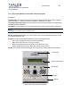
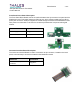
Rear Panel
48-pin DIN
Ground/Alignment stud
IF Input
LO#1 Input
RF Output
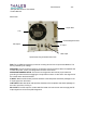
Fan
Upconverter Plug-in Module Rear View
FAN: The 18 CFM Fan assembly is used as a cooling device for the Upconverter Module. The
Fan is powered by DC voltage.
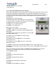
48-PIN DIN: The 48-pin DIN connector is an interface point to the Driver Section backplane that
includes the power, control, and diagnostics functions of the Driver.
GROUND/ALIGNMENT STUD: The Ground and Alignment Stud ensure proper electrical
grounding is achieved before engaging the 48-pin DIN connector. It also aids in the alignment of
the module within the Sub-Chassis.
IF INPUT: Male 50: blind mate provides interface to the backplane and allows passage for the
IF input signal from the exciter.
LO#1 INPUT: Male 50: blind mate provides interface to the backplane and allows passage for
the LO#1 input from LO Plug-In
RF OUTPUT: The RF Output is a male 501 blind mate connector that is used to supply the RF
output signal to the Power Amplifier Segments.