
User's Manual Part 2

Driver Section - 94 -
®
Affinity LBD-200C-N1 Transmitter
Product Manual
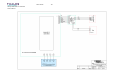
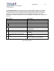
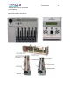
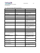
Front Panel Samples
Sample Name Coupling Factor
2
nd
IF Sample -45+/ -2 dB Front Panel access through an
SMA 501 Female Connector
Loaded with 501 termination
when not is use
RF Sample 470 MHz
860 MHz
-30+/-4 dB Front Panel access through an
SMA 501 termination when not
in use
DC Power Requirements
Voltages/Current
+12V
DC .5 @ 2.8A max
+8V
DC .5 @ 1.0A max
-12V
DC .5 @ 150ma max
Connector 48 conductor, 3amps/circuit
minimum
Interfaces to back-plane
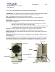
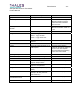
Environmental
Cooling Forced air-cooled, minimum of 18
CFM required
Forced air-cooled drawing
ambient air through the intake on
the front of the Pre-Amplifier
Plug-In Module and exhausting
out the rear of the module
Operating Temperature
0qC to 50qC
Relative Humidity 0 to 95% non-condensing
Alarms Indicators/Adjustments Controls
RF Output Failure Alarm DRIVER FAILURE Low (TTL
Low)=RF Output Failure
Signal available at back-plane
Over Temperature Alarm DRIVER FAILURE Low (TTL
Low)=Over Temperature
Signal available at back-plane
In Signal Indicator YES (when present) or NO (when
absent)
Visible via LCD Display
Transmit Indicator XMIT (when RF power is
present) or No Pwr (when RF
power reads 0%)
Visible via LCD Display
Power Supply
Status/Measurements
PASS or FAIL/ V scale Visible via LCD Display
RF Power Measurements % Scale Visible via LCD Display