
User's Manual Part 2

Exciter Configuration Description - 58 -
®
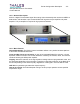
Affinity LBD-200C-N1 Transmitter
Product Manual
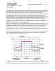
The proprietary clipping function limits the magnitude of the vector above a given threshold. The
magnitudes higher than the threshold are replaced by the threshold complex value. This allows
for a better quality output signal at a lower back-off compared to other transmitters.
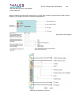
The non-linear automatic precorrection function computes the best shoulder level at the output
of the transmitter. The process is based on a Look Up Table (LUT) that is loaded from an
iterative measurement of the shoulder level. The Digital Adaptive Pre-correction (DAP
TM
) inputs
the I and Q signals from the Digital board and compares them to reference I and Q signals
derived from the output of the transmitter. The DAP™ precisely calculates the correction
needed to make the output signals match the original input signals, and then updates the
forward path in both amplitude and phase to compensate for any differences. The outputs of the
DAP
TM
board are the fully corrected I and Q signals.
The DAP
TM
compensates for non-linear distortions, and is able to adapt to drift changes in the
transmitter. Since the correction is adaptive, the set-up and maintenance of the transmitter will
not require a significant investment in time and test equipment, unlike equipment without
adaptive features, the DAP™ signal quality is maintained at all times. Over the lifetime of the
equipment, DAP™ is proven to save operators time and money with lower maintenance costs.
The complex base-band outputs of the LUT are then up-converted to an intermediate frequency
(IF). The complex IF frequency signals are converted to the analog domain, amplified and
transposed to the proper VHF, UHF, or RF band.
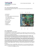
A daughter board located on the TS Board performs the Complex Up/Down Conversion (CUDC)
function. The Complex Up/Down Converter (CUDC) receives the pre-corrected signals from the