
User's Manual Part 2

Driver Section - 91 -
Affinity
®
LBD-200C-N1 Transmitter
Product Manual
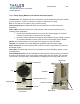
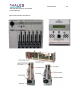
The Front panel PCB has a serial port that can be used for testing, adjusting or controlling
most of the plug-in functions. A personal computer and application program is required to
accomplish this task. The front panel keyboard and display board provide a user interface
capable of controlling a limited number of functions inside the Upconverter, and for the
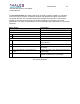
presentation of a series of measurements in the LCD display. See Table below for a list of user
interfaces.
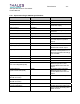
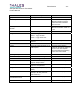
Menu display Description
Greeting Displays “Thales Broadcast & Multimedia”
State Control
Mode Local/Remote
Operate State On-Air/Standby
System Status Displays the Upconverter Module status
Power Supply Status Displays the top level status of the Power Supply
Plug-In Module
Upconverter Module “In Signal” Displays the ON/OFF status of “In Signal”
Upconverter Module “System Forward Power” Displays the value of “System Forward Power” in
percentage
Upconverter Module “System Reflected
Power”
Displays the value of the “System Reflected Power”
in percentage
Upconverter Module “Forward Power” Displays the value of the Upconverter Module
internal “Forward Power” in percentage
List of User Interfaces