
User's Manual Part 2

Driver Section - 90 -
Affinity
®
LBD-200C-N1 Transmitter
Product Manual
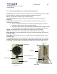
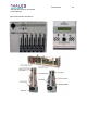
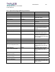
Intermediate Power Amplifier (IPA) sub-module
After exiting the ALC module the signal is amplified by 13 dB by the IPA. The IPA Sub-Module
contains a temperature sensing circuit that outputs to the MCU, via the Distribution board,
voltage levels that are proportional to the temperature of the upconverter plug-in. The final RF
signal exits the rear of the upconverter plug-in.
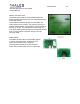
ALC Sub-Module
The ALC Sub-Module located internally in the Upconverter Module, containing both integrator
and Positive Intrinsic Negative (PIN) attenuators, uses a closed-loop level controller to
compensate for PA Module gain variation, and regulates overall output power. The closed-loop
level controller works by receiving voltage samples from the output of the Envelope Detector
Module proportional to the transmitter output power, comparing this voltage to an internal
reference, and adjusting the gain to compensate for PA Module output gain variation. This
compensation ensures the transmitter power level remains constant. Indication of forward and
reflected power levels of the transmitter and forward power level of the Upconverter module are
displayed on the LCD assembly once information originated in respective power detection
modules are routed to, and then processed by, the MCU.
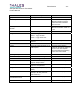
The Connector Interface board provides +12, -12, and +8V
DC to the respective sub-modules
and routes forward and reflected detected power voltages for further processing. This board is
also the conduit through which serial data is exchanged between the Upconverter Plug-In
Module and the rest of the system.
Temperature Sensor board
Receives voltage proportional to the temperature generated by a temperature sensor typically
placed on the last power amplification stage.