
User's Manual Part 2

Driver Section - 88 -
®
Affinity LBD-200C-N1 Transmitter
Product Manual
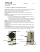
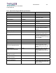
11.2 Upconverter Module
The Upconverter Module is a plug-in assembly mounted within the Driver Section of the
Affinity®. The basic function of the Upconverter Module is to convert and amplify the exciter
output to the proper power level required to drive the subsequent final amplification stage. To
accomplish this, the appropriate level IF signal, local oscillator signal(s), and power supply
voltages must be present on this plug-in.
The Upconverter performs ALC on the RF signal maintaining a constant drive level after the first
conversion stage. The Upconverter Module is attached to the main chassis via three slide-rails
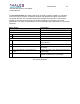
and two thumbscrews. Several internal assemblies make up the Upconverter Module including:
x Microcontroller Unit (MCU)
x Front panel board
x Distribution board
x ALC Module
x Converter Sub Module
x Band Pass Filter
x Temperature Sensor Board
x Intermediate Power Amplifier
x Connector Interface
x LCD board
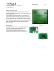
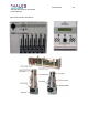
These internal boards are accessible through two detachable covers. The covers, together with
the rear panel Fan Assembly, are part of the forced-convection cooling system.
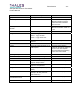
Theory of Operation
RF signals are sent to and from the Upconverter Module through coaxial connectors and cables
on the back panel. Power and communication signals go through a 48-pin connector interface
located on the rear panel. RF signal is delivered to the internal modules of the Upconverter via
coaxial cables utilizing floating connectors. Signal traffic other than RF, such as power supply
voltages, detected power voltages, and serial data from the Microcontroller Unit, are distributed
between the modules using the Distribution board and connecting harnesses.
The Microcontroller Unit (MCU) contains firmware that controls and monitors the top-level status
of the transmitter, and indicates status of the Driver Power Supply and Upconverter modules,
and the transmitter forward and reflected power. The MCU provides an interface to the Front
panel board switch assembly and the LCD board. The switch assembly is used to scroll through,
and enter the user-interface options. The front panel switch assembly (keypad) has limited
ability to make system or Upconverter module control functions; main calibration is done via the
RS-232 port on the Upconverter. The LCD assembly provides a visual status of the menu
navigation. The UHF signal from the output of the exciter is delivered to the UHF input of the
Upconverter and then routed to the Converter sub-module.