
User's Manual Part 2

Driver Section - 86 -
®
Affinity LBD-200C-N1 Transmitter
Product Manual
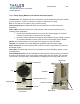
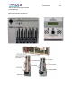
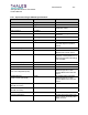
11.1.2 Power Supply Module Front and Rear Panel Descriptions
Thumbscrews: This hardware secures the module to the sub-chassis and provides a reliable
ground connection. Loosen to remove the module for replacement or repair.
Fan: An 18-CFM V
DC fan used for plug-in module cooling.
Communication Port: The RS-232 serial communication port is used for setup and
diagnostics.
Power LEDs: The Power LEDs are a visual indication used for status monitoring of the
operating power parameters.
x Power: Green indicates power from the Front-End Power Supply. An unlit LED
indicates no power from the Front-End Power Supply.
x DC Power: Green indicates Power Supply Plug-In Module output voltage is present.
An unlit LED indicates no output power from the Power Supply Plug-In Module.
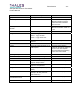
Handle: The handle assists in removing the Power Supply from the sub-chassis.
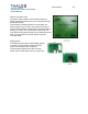
Heatsink: The heatsink aids in heat dissipation generated within the Power Supply.
Power Connector: The 6-pin header power connector is used to input power from the Front-
End Power Supply.
48-Pin DIN: The 48-pin DIN connecter is an interface point to the backplane (power, control,
and diagnostics).
Ground/Alignment stud: The Ground/Alignment stud ensures proper grounding is achieved,
and aids in the alignment of the Power Supply module within the sub-chassis. The stud also
ensures that circuit grounding is made before the engagement of the 48-pin DIN connector.
Front Panel
Rear Panel
Handle
Communication Port
Power LEDs
Fan
Thumbscrew
Power Connector
Ground/Alignment stud
48-pin DIN
Heatsink