
User's Manual Part 2

Exciter Configuration Description - 57 -
®
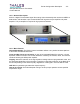
Affinity LBD-200C-N1 Transmitter
Product Manual
x Transport Stream Identification
x Data Randomization
x Reed-Solomon Encoding
x Data Interleaving
x Trellis Coding
x Grey mapping
x FFT
x Pilot Insertion
x Guard interval insertion
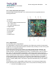
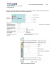
The main objective of the Digital Board is to generate an output complex signal in the form of
parallel I and Q digital signals. In addition, the Digital Board provides the clock reference for all
the other boards within the DVB-H exciter. The system is fully compliant with the EN 300-744
1.5.2 Digital Television Standard.
Additional optional functions such as a built in GPS receiver, or DVB receiver, are supported by
additional daughter boards managed by the embedded microprocessor.
This version is designed 3-Mgate FPGA hardware and is dedicated to DVB-H. The incoming
serial data stream signal is processed by the channel encoder, which provides an output
complex digital signal in the form of parallel I and Q digital signals, and a clock reference. The
channel encoder has a hardware version allowing performance of DVB-H modulation. For DVB-
H, all standard modes are supported including hierarchical modes. The equipment can support
redundant switching input for DVB operation. The equipment is also capable of managing either
single frequency networks (SFN) or multi frequency networks (MFN) operation. Bit Rate
Adaptation with PCR re-stamping is used for MFN operation. An embedded microprocessor
manages daughter boards such as a global positioning satellite (GPS) receiver, DVB-H receiver
and TS Board. RS232, I2C and SPI buses are used for internal control and monitoring of the
daughter boards. External control and monitoring is done through RS232 and/or Ethernet and/or
CAN bus. The digital board distributes pilot clocks to Sirius boards, 10MHz to the synthesizer
and TS Board, and system clock to the TS Board.
10.1.5.2 TS Board
Functional Description of TS Board
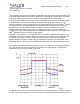
The “TS Board” is also equipped with an FPGA. It supports the up-conversion and adaptive pre-
correction processing. The TS Board receives the I/Q base-band signal and the clock reference
from the Digital Board. The TS Board performs the following processing:
x Clipping
x Non-Linear Digital Adaptive Precorrection
x Linear Equalization