
User's Manual Part 2

Driver Section - 81 -
®
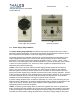
Affinity LBD-200C-N1 Transmitter
Product Manual
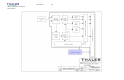
The input buffers for the current sampling provides the voltage samples. Dividing resistors scale
down the buffer outputs. This provides a sample voltage to the analog-to-digital converters that
is mid-range between 0 and 5 volts.
All of the power supply sections operate in a similar manner. The -12V
DC power supply section
uses inverting amplifiers (instead of buffers) with unity gain to convert the sample values to
positive representations of the sampled voltages.
The current and voltage sample outputs are applied to an analog multiplexer integrated circuit.
This chip selects the group of signals that are applied to the microprocessor from a control
provided from the microprocessor.
An onboard Master Control Unit (MCU) with programmable firmware provides monitor and
control functionality. The MCU monitors the voltages and current from the power supply and
controls the output based on reference measurements. The MCU will switch off positive
voltages to the Driver Section when a loss of negative voltage is detected. This feature protects
the amplification devices located within the Upconverter and Power Amplifier modules.
The Power Supply Plug-In Module controller routes RS-485 multi dropped network
communications to other modules on the network.
A temperature sensor within the Power Supply Plug-In Module provides input to the
microcontroller proportional to the ambient temperature of the module. If the Power Supply
Plug-In Module operates over the temperature specification, a controlled shutdown of all
supplies will occur.
The Power Supply module contains an RS232 interface located on the front panel. This EIA
standard interface allows for connectivity with a serial host such as a desktop computer.
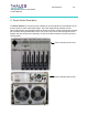
The Power Supply Plug-In Module is “Hot Swap” compatible allowing for module replacement
without the need of powering down the module or transmitter.
NOTE: During the “Hot Swap” process as the Power Supply Plug-In Module is removed, the
transmitter will go off air until the replacement Power Supply Plug-In Module is plugged back
into the chassis.
The Power Supply Plug-In Module is cooled by a single fan and is mounted in an extrusion that
is designed to dissipate the heat generated from the components within. The fans of the Sub-
Chassis also ventilate the Power Supply-Plug-In Module.