
User's Manual Part 2

Exciter Configuration Description - 56 -
®
Affinity LBD-200C-N1 Transmitter
Product Manual
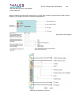
10.1.5 Sirius Subassembly Description
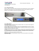
The Sirius DVB-H Exciter is housed in a “19” 2U EIA rack unit and is populated with the
following assemblies:
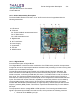
A- LED board
B- TS board
B1- Enhanced QoS measurement board
B2- IF Filter board
B3- UHF transmitter board
C- Digital board
D- AC Transformer
E- Power Supply
F- Synthesizer
G- PC Slot
H- GPS Receiver
10.1.5.1 Digital Board
Functional Description of Digital Board
The “Digital Board” is built around the combination of an FPGA and a powerful microprocessor.
It supports most of the input/output interfaces and base-band processing from the incoming data
stream up to an I/Q base-band output.
The transport stream input signal is based on the DVB-H Digital Television Standard. The
exciter includes Dual A and B asynchronous serial interface (ASI) inputs in a 75-ohm BNC
female connector, conforming to DVB-ASI (TR 101211). The ASI format is a 188, 214 burst or
byte mode. The equipment adapts automatically to the net input rate since the input rate is
lower than the channel capacity. The dual inputs can be configured as redundant ASI switched
inputs. The DVB-H RF exciter has built in capability to monitor the presence and consistency
(synchronization bytes) of the incoming TS, and produce appropriate alarms. This feature
includes MIP identification (DVB standard), in single frequency network (SFN) as well as multi
frequency network (MFN) modes. This function is performed simultaneously on each different
ASI input.
The equipment is able to manage MFN or SFN operation. The incoming serial data stream
signal is processed by the DVB-H channel encoder, which performs the following functions:
x Removal of the MPEG sync byte