
User's Manual Part 2

Exciter Configuration Description - 73 -
®
Affinity LBD-200C-N1 Transmitter
Product Manual
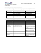
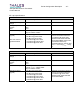
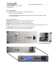
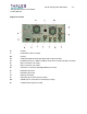
Right side of Rack
K- Cooling
L- Synthesizer 1GHz LO output
M- Cooling
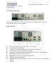
N- 0 dBm with 45dB shoulder RF output (without precorrection)
O- Feedback RF input (-15dBm+/-5dB) for linear and no linear automatic correction.
P- GPIO connection (not used)
Q- GPIO connection (not used)
R- CAN bus in connection with Digital Board (not used)
S- DVB-ASI input TS #1
T- DVB ASI input TS #2
U- Optional ASI output
V- Automatic gain control input (not used)
W- VSWR input in connection to TS Board (not used)
X- 10 MHz output signal (not used)