
User's Manual Part 2

Exciter Configuration Description - 72 -
®
Affinity LBD-200C-N1 Transmitter
Product Manual
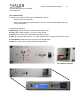
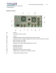
10.1.7 Exciter Connectivity
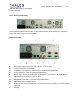
Located at the backside of the exciter are the interconnection points used by the operator to
control the driver function in the transmitter.
Left side of Rack
A- Main power supply input: 90 to 254 volts AC, 47 to 53 hertz
B- 2 RJ45 connections for Ethernet
C- 10 MHz 50 ohm frequency reference input connected to Digital Board
D- Timing reference 1 PPS connected to Digital Board
E- Double input and double output opto-coupled ports in connection with Digital Board
F- DB9 RS232 UTC reference input for GPS
G- DB9 RS232 Local CM in connection with Digital Board.
H- DB9 RS232 data for Digital Board.
I- Multipoint connection I/O extension, monitoring and control interface via contact closure
(optional)
J- Cooling