
User's Manual Part 2

Exciter Configuration Description - 71 -
®
Affinity LBD-200C-N1 Transmitter
Product Manual
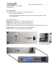
10.1.6 Exciter Rack
The frame of the exciter includes two complementary devices:
Exciter Front Panel Assemblyx
x PC Card Slot Assembly (optional) used to house a memory board capable of saving
exciter parameters.
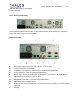
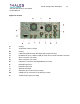
Front Panel Designators
A-Monitoring- Output sample to monitor the RF signal output
B-Fault (LED)- Global detection---checks for faulty boards
C-Alarm (LED)- Checks input data stream and GPS operation
D-OK (LED)- LED has two functions: (1) Power supply presence voltage (2) Start-up of exciter
E-Com1 RS232- RS232 input for programming the Digital Board.
F-LAN- Ethernet access for programming the Digital Board
PC Card Slot (optional)