
User's Manual Part 2

Exciter Configuration Description - 69 -
Affinity
®
LBD-200C-N1 Transmitter
Product Manual
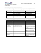
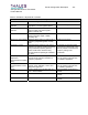
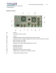
Alarms / Indicators / Adjustments / Controls
Alarms/ Indicators/Adjustments/Controls
Parameters Specifications Comments / Notes
DC PWR Presence
Indicator
Green LED, ON= +12VDC power present;
trips when + 12 VDC signal is absent
Visible via front panel
Frequency reference
Indicator
Red LED, ON = External Frequency
reference fault; trips when signal < -
5dBm; normally unlit
Visible via front panel
Level Indicator Red LED, ON= output muted or at low
power; trips when signal <+6dBm;
normally unlit
Visible via front panel
Phase () Lock Indicator
Red LED, ON= Loss of Lock or loss of
frequency programming data; normally
unlit
Visible via front panel
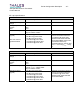
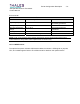
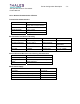
Frequency Control Serial interface; Selection of the output
frequency is made by serial programming
using ANACAD proprietary protocol,
which sends ASCII character string
across serial bus operating at 1200buad;
no parity.
Accessible via rear panel serial
connections on 60pin DIN; It will
also be possible to read back the
frequency setting of the
synthesizer.
Frequency Reference
adjustment
(internal reference option
only)
Firmware controlled user adjustment of
internal OCXO reference oscillator for
frequency alignment
Accessible via RJ11 front panel
port use external computer with
LO calibrator application
Front panel
communication/ Control
port
RS-232 interface; used for firmware
upload, setup, calibration, control, and
diagnostics purposes.
Accessible via RJ11 front panel
port use external computer with
LO calibrator application
Reset Control signal input to module; pull-up to
+5V = reset condition
Signal available at rear-panel of
module
Reference int/ext TTL Low = internal ref; HIGH=external ref Signal available at rear-panel of
module
LO Fault TTL Low = fault condition; HIGH=Normal Signal available at rear-panel of
module