
User's Manual Part 2

Exciter Configuration Description - 68 -
Affinity
®
LBD-200C-N1 Transmitter
Product Manual
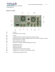
General
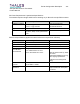
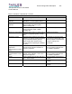
Parameters Specifications Comments / Notes
Power Level
Main output
Sample output
+12dBm, r2dB
-7dBm, r3dB
No ALC
Power Level (muted)
Main output
Sample output
<-25dBm
<-43dBm
Time to mute <2ms Hardware controlled
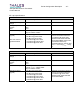
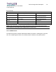
Frequency settling time
After switch on
After last character is
received in a channel
change event
<1s
<700ms
Stability Based on frequency reference; 10
-9
to
Allan variance
Harmonics 10dBc minimum
Connector / Impedance
Main output
Sample
DIN connector female coaxial contact / 50
:
DIN connector female coaxial contact / 50
:
Mates with backplane
I/O VSWR 2:1 Ratio
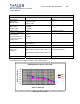
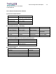
The UHF phase noise mask is shown in the following figure:
10 -65 -80
100 -85 -94
1000 -90 -101
10000 -95 -104
100000 -115 -120
1000000 -135 -140
UHF Synthesizer phase noise mask
-160
-140
-120
-100
-80
-60
-40
-20
0
1 10 100 1000 10000 100000 1000000
SSB Freq Offset (Hz)
SSB noise (dBc/Hz)
Mas k
Typical
UHF phase noise mask