
User's Guide


Affinity System Reference & Theory of Operation 30
Affinity Control User’s Guide
Software v2.50
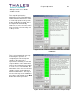
using the Affinity Control software. The 15% trip level can also be adjusted within the
Metering/Display Calibration screen accessible from the Maintenance window.
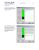
The LCD display on the upconverter module provides rudimentary displays of forward power
(percent), reflected power (percent), and upconverter internal forward power (percent). The
forward and reflected power displays are calibrated to the forward and reflected power samples
obtained from the RF system. The upconverter internal forward power reading is obtained from
a measurement circuit inside the upconverter module. This reading may vary substantially, even
after calibration, as the upconverter adjusts its output power to maintain a constant system
output power in ALC Auto mode. All three display readings can be calibrated using the Affinity
Control software. In addition, minor adjustments can be performed in the Metering/Display
Calibration screen.
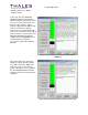
Finally, the upconverter module provides an overpower limit control. This power limiter can be
set as desired to limit the maximum system output power via the Power Limiter value with the
Affinity Control software.
NOTE: For 250W or lower power, the forward and reflected power samples are obtained internally to the
transmitter chassis. In order to adjust those levels (…which should NOT be necessary), the rear panel of
the transmitter chassis must be opened. This will be necessary when calibrating the reflected power
sample, since the forward power sample is fed to it for 100% calibration.
3.3 Affinity Power Amplifier(s) Reference
The power amplifiers in the Affinity system provide the high power output. The number of
amplifiers in the system is dependent on the system’s rated output power. The amplifiers have
an internal microcontroller to monitor their operation. Should a fault condition be detected, the
amplifier output will be shut down and the status LED on the amplifier module will turn RED. In
addition, a logic board monitors amplifier status and reduces system power (in ALC Auto mode)
when an amplifier fault is detected. The power reduction level is dependent on the number of
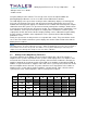
amplifiers in the system and the number amplifiers currently faulted. Table 1 lists the various
system power levels, faulted amplifiers, and associated power reduction.
Faulted Amplifier Count
Power
1 2 3 4 5 6 7 8
50W
Off
100W
-6dB Off
200W
-3dB -6dB Off
250W
-3dB -6dB Off
500W
-1.5dB -3dB -6dB -6dB Off
1kW
-1.5dB -1.5dB -3dB -3dB -6dB -6dB -6dB -6dB
Table 1 Amplifier Fault Power Reduction Levels (in ALC Auto mode)