
User's Guide


Affinity System Reference & Theory of Operation 29
Affinity Control User’s Guide
Software v2.50
3 Affinity System Reference & Theory of Operation
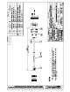
Refer to the Affinity Simplified Block Diagram in Figure 43
3.1 ADAPT Reference
The ADAPT performs the on-channel generation of the 8VSB RF signal. It also performs all
linear and nonlinear precorrection of the RF signal. The remote interface to the Affinity system
for RF output ON/OFF, Raise/Lower, and Correction, is provided through the user interface
module in the ADAPT chassis. The recommended RF output level of the ADAPT is between +6
and +7dBm. The RF output of the ADAPT chassis is fed to the RF input of the upconverter
module.
3.2 Affinity/Upconverter Theory of Operation
The upconverter (amplifier) module provides sufficient amplification of the on-channel signal
from the ADAPT to drive the high power amplifier(s). When used in ATSC service, the term
"upconverter" is actually is misnomer since the unit does not perform any frequency
upconversion, the output of the ADAPT exciter already being on the desired UHF channel. That
is, the upconverter function is disabled, and the module functions as a simple preamplifier and
transmitter controller.
The upconverter module provides RF output level control of the Affinity system. A sample of the
forward power taken from the RF system is fed back to the upconverter and calibrated at the full
power level of the system. This ALC control is capable of overcoming small variations in the
output of the ADAPT, such as occurs when non-linear correction is performed. This parameter
is calibrated using the Affinity Control software. The output level can be adjusted from the Main
Control screen of the Affinity Control software by means of the ALC Auto Ref value.
Figure 43 Affinity System Simplified Block Diagram
The upconverter also receives a reflected power sample from the RF system. The upconverter
is calibrated to reduce output power by 6dB when a 15% reflected power level is detected at the
transmitter output. If a 25% or greater reverse power level is detected at this reduced power
level, the upconverter will turn off the RF output completely. These trip levels can be calibrated